How TCUP Calls Work
The Trivial Call Up Protocol, or TCUP, was designed with some key goals in mind, the first being simplicity. Second, TCUP had to survive as a P2P protocol in a world that is full of firewalls and is on the verge of changing network address spaces. As a result, TCUP is truly a network unto itself overlaid on top of the existing internet. The beauty of the TCUP design is that it has truly no centralization and nominal organization. The drawback is that it cannot, on its own, scale to millions of nodes. Users may organize TCUP networks using upper layer protocols, much the way the Internet is organized by upper layer protocols, but TCUP is your network to do with what you will. The assumption is that your network won't typically be the size of the Internet. On the other hand, knowing how TCUP works "under the hood" can give the moderately network-savvy user a huge edge in making some conscious decisions about how to build parts of their TCUP network which will allow it to grow very large without adding those managerial upper layer protocols.
Following is a simple introduction to the TCUP topology followed by a technical walk-through of how a Call is made. Most people familiar with overlay networks can probably skip the first section.
The complexity of TCUP is not in its implementation requirements but keeping strait the four different views of connectivity involved in the TCUP network, those types of connections being lower-layer protocol connections, Connections, Channels, and Calls.
Lower-layer protocol connections are typically the TCP connections that link one TCUP node to another. They are almost synonymous with Connections and often can be used interchangeable. The difference is that a lower-layer network connection implies the lower layer network path as well while a Connection ignores that TCP and IP are used, ignores routers, paths, etc. The benefit is that TCUP can be run over any streaming transport (like TCP Unix Sockets, etc). TCUP does not need to be rearchitected to accommodate the new, larger IPv6 address space or any future network layer protocol. The draw back, though, is that TCUP cannot leverage network addresses to select a more efficient connection. The more bits IP addresses share in their prefix, typically, the faster the connection and the shorter the path between those two IP addresses is. This is the idea behind hierarchical routing on the internet, but TCUP cannot take advantage of this information. The user must either architect an upper-layer protocol to control and manage the TCUP layer or the user must design the network links not unlike how Internet routers are manually configured.
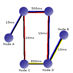 As an example, consider the graph to the right. It shows a network of nodes all connected with black network links each having an assigned delay value in milliseconds. On top of those black lower-layer protocol links are colored paths representing Connections made by the TCUP protocol. TCUP has no information about the black links, their delays, how many hops it takes to get to the next node, or if there exist other paths to nodes. As far as the TCUP Connections are concerned, Node A connects to Node B, Node B connects to Node C, and Node C connects to Node D. For Node A to communicate with Node D a lot of links need to be crossed multiple times and an incredible delay time is incurred. The lesson to take home from this is that if a large scale TCUP deployment is being undertaken a lot can be gained by architecting it.
Some obvious improvements would be to have Node A connect to Node D directly. Node B should also connect directly to Node D. Notice that these two changes make D the center of a star topology. If Node D is powerful enough to handle the throughput for the whole network, this is a great design choice. If D is a small work station, then perhaps it would be wise to add some redundant links to the network. Remember that performance depends on not only avoiding redundancy but how resources are allocated. In this case, D necessarily handles most of the traffic for any node-to-node communication. Before it only had to handle traffic destine for itself on the TCUP layer.
The sorts of problems brought up in this example are typical for any sort of overlay network. Some deployments will never see these problems. Lightly connected networks in the same subnet will probably work very well regardless of who is connected to who. Deployments that span many subnets, though, could benefit from some human insight or a small upper-layer protocol to add some smarts to the system.
The next two ways to view connectivity in TCUP, like lower-layer protocol connections and Connections, are related closely to each other. Before getting to that, though, it is important to understand one of the inefficiencies of TCUP. The basic type of communication in TCUP is a message. Messages have a type, a length, source address, a destination address, an id, and a hop count. TCUP nodes are to forward messages they receive. There are some rules about when and when not to forward a message, but typically, a TCUP node will forward any message it receives out on all connections except the connection it received the message on. There are, though, many times when a TCUP node knows that it will be talking with another node a lot. Consider a web server implemented over TCUP. Many HTTP/1.1 requests could be sent to a node running the server. It makes no sense to forward messages too and from the two nodes involved in the HTTP session to other nodes that have nothing to do with relaying the data to the appropriate node. To solve this problem Calls where added to TCUP. Information sent on a Call will traverse the same path to and from the two nodes that terminate the Call.
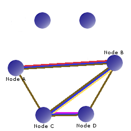 Obviously, each node in the path must know about this Call in order to send information that comes in from one node to the next node in the path. Since TCUP is totally distributed and has no central information repository each node must refer to a Call by some local identifier or identifiers. The way TCUP nodes locally refer to Calls is by splitting them into and upstream and a downstream Channel. That is, a Channel to the next node in the path down to the destination node and a Channel that goes upstream to the node that originated the Call. Channels are single node-to-node hops along a Call as illustrated in the graphic to the right. The TCUP connections between Node A, B, C and D are in brown. The blue line is a Call from A to D. Notice at each hop there is another colored line representing the Channel. If A is the originating node then we say that Node B has a downstream Channel which is represented by the yellow line and an upstream Channel represented by the red line. Notice, by the way, that this is the same network as in the previous illustration but with a few extra TCUP Connections and the lower-layer protocol connections removed.
In the previous section the four basic ways to look at connectivity were discussed. There are Calls that are composed of Channels which traverse Connections and those Connections are made by lower-layer protocol connections. What was intentionally skipped over was the guts of a Call. How is a Call setup? How does a Call label data and move it around a TCUP network?
For reference, here is what a CallUp message looks like...
 0 0 0 0 0 0 0 0 0 1 1 1 1 1 1 1 1 1 1 2 2 2 2 2 2 2 2 2 2 3 3 3
 1 2 3 4 5 6 7 8 9 0 1 2 3 4 5 6 7 8 9 0 1 2 3 4 5 6 7 8 9 0 1 2
+---------------+---------------+-------------------------------+
|      0x01     |     0x03      |            msg id             |
+---------------+---------------+-------------------------------+
|      hops     |               message length                  |
+---------------+-----------------------------------------------+
|                          to node id                           |
+---------------------------------------------------------------+
|                         from node id                          |
+---------------------------------------------------------------+
|                   timeout in milliseconds                     |
+---------------------------------------------------------------+
|                        from channel id                        |
+---------------------------------------------------------------+
... and a CallEstablished message...
 0 0 0 0 0 0 0 0 0 1 1 1 1 1 1 1 1 1 1 2 2 2 2 2 2 2 2 2 2 3 3 3
 1 2 3 4 5 6 7 8 9 0 1 2 3 4 5 6 7 8 9 0 1 2 3 4 5 6 7 8 9 0 1 2
+---------------+---------------+-------------------------------+
|      0x01     |     0x05      |            msg id             |
+---------------+---------------+-------------------------------+
|      hops     |                     0x00000c                  |
+---------------+-----------------------------------------------+
|                            channel id                         |
+---------------------------------------------------------------+
We will refer back to these several times.
Lets start at the beginning of a Call. The user tells the TCUP protocol API to make a call to some node, n. The originating node generates half a Channel. Normally a Channel consists of a Connection and an id but the Connection that will be used in this Call is not yet known. It will be determined when a CallEstablished is received but now must be left blank. The CallUp message is then sent out on all available Connections.
A node receiving a CallUp message pulls out the from channel id and along with the Connection on which the CallUp message was received, constructs the upstream Channel. The Call, however, is not yet established and may fail to be established via this node. The node must keep an eye on this data and if it does not get paired with an downstream Channel which results from a CallEstablished message, it must be thrown away after a suitable timeout. Note, the timeout value contained in the CallUp message is the timeout after which an idle Call is destroyed, not a timeout for how long the node should keep the half-up Call around.
After making the upstream Channel the node should decrement the hops values in the message, generate a channel id on which this node will accept the CallEstablished message and subsequent data destine for this Call, set the from channel id to this new value, and forward the message out on all interfaces except the one on which it received the message. Notice that the other fields in this message remain unchanged. The to node id, from node id and the message id are used to prune loops in the network and must not be changed by any forwarding node. The node may reduce the timeout value if it will destroy call records before the specified timeout is reached.
Finally, after some number of hops the CallUp message should reach the node specified in the to node id field. At this point the node should consume and not forward the message any more. This node then creates a Channel id on which it will receive data related to this Call and sends a CallEstablished message from the Channel id back along the channel id specified in the CallUp message.
When a node receives a CallEstablished message with a destination id in it the recieving node looks up the half-up Call that it constructed when it was forwarding the CallUp message, fills in the Connection data that was left blank, and generates another Channel id to be used on data going down stream. It replaces the channel id field in the CallEstablished message with its downstream Channel id and sends it out the Connection specified in the upstream Channel.
In this way the CallEstablished message crawls its way back along the path that the CallUp message took completing all the information needed at each node. Something that should be noticed are first, that ids are not generated by the node that will use them to send information but the node that receives information. If the node that sent the data was able to set the id by which it would mark all data associated with a Channel then each node must generate a unique Channel id for each Connection a CallUp message goes out on or the protocol runs the risk of having two nodes use the same id for a Channel. Secondly, the intermediate nodes do not keep the source and destination node id around. They are only concerned with mapping incoming traffic on one Connection to another id on an outgoing Connection. Notice finally that there is also no way in TCUP to repair a broken Call. If a Channel breaks for some reason, the node crashes, the link goes down, the Call is lost and must be reestablished using different nodes. This does not mean that there are not algorithms that could be applied, but this is again left to the upper layer protocols and API implementation to work on.
- Call
- A bidirectional path along a graph of Connections linking some node A with some node B.
- Channel
- A Connection that is a member of a Call and the ids each adjacent node uses to mark data sent in that Call this Channel is a member of.
- Connection
- The link to an immediately neighboring TCUP node.